Defined in 802.15.4 standardThe IEEE 802.15.4 defines the physical (PHY) layer and the Medium Access (MAC) layer. The specification for the PHY defines a low-power spread spectrum radio operating at frequency bands such as 2.4 GHz, 915 MHz and 868MHz.
Radio Network Controller
Published on Feb 20, 2020
Abstract
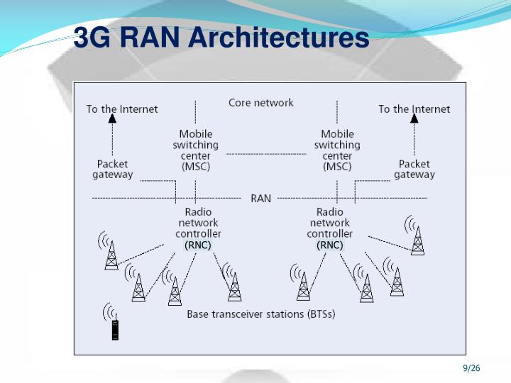
A Radio Network Controller (RNC) provides the interface between the wireless devices communicating through Node B transceivers and the network edge. This includes controlling and managing the radio transceivers in the Node B equipment, as well as management tasks like soft handoff.
The RNC performs tasks in a 3G wireless network analogous to those of the Base Station Controller (BSC) in a 2G or 2.5G network. It interfaces with GPRS Service Nodes (SGSNs) and Gateways (GGSNs) to mediate with the network service providers.
A radio network controller manages hundreds of Node B transceiver stations while switching and provisioning services off the Mobile Switching Center and 3G data network interfaces. The connection from the RNC to a Node B is called the User Plane Interface Layer and it uses T1/E1 transport to the RNC.
Due to the large number of Node B transceivers, a T1/E1 aggregator is used to deliver the Node B data over channelized OC-3 optical transport to the RNC. The OC-3 pipe can be a direct connection to the RNC or through traditional SONET/SDH transmission networks.
A typical Radio Network Controller may be built on a PICMG or Advanced TCA chassis. It contains several different kinds of cards specialized for performing the functions and interacting with the various interfaces of the RNC.
More Seminar Topics:
Smart Dust,Stealth Technology,Surround Systems,Tamper Resistance,Teleportation,Trustworthy Computing,Turbo Codes,Ultrasonic Transducers,Wardriving,Wireless Internet,Modems and ISDN,Modular Embedded Internet Software Support,Motes,M-Voting,Nanorobotics,Nuclear Micro Generator,Opaque Networks Utilizing TOS,Optical DSP,Optical Free Space Communication,Photovoltaic,Pivot Vector Space Approach in Audio-Video Mixing,PLEDS,Rapid Prototyping,Real Time Systems with Linux/RTAI,Fractal Image Compression| OSI model by layer |
|---|
|
|

The Radio Resource Control (RRC) protocol is used in UMTS and LTE on the Air interface. It is a layer that exists between UE and eNB and exists at the IP level. This protocol is specified by 3GPP in TS 25.331[1] for UMTS and in TS 36.331 [2] for LTE. RRC messages are transported via the PDCP-Protocol.
The major functions of the RRC protocol include connection establishment and release functions, broadcast of system information, radio bearer establishment, reconfiguration and release, RRC connection mobility procedures, paging notification and release and outer loop power control.[3]By means of the signalling functions the RRC configures the user and control planes according to the network status and allows for Radio Resource Management strategies to be implemented.[4]
The operation of the RRC is guided by a state machine which defines certain specific states that a UE may be present in. The different states in this state machine have different amounts of radio resources associated with them and these are the resources that the UE may use when it is present in a given specific state.[4][5] Since different amounts of resources are available at different states the quality of the service that the user experiences and the energy consumption of the UE are influenced by this state machine.[5]
RRC inactivity timers[edit]
The configuration of RRC inactivity timers in a W-CDMA network has considerable impact on the battery life of a phone when a packet data connection is open.[6]

The RRC idle mode (no connection) has the lowest energy consumption. The states in the RRC connected mode, in order of decreasing power consumption, are CELL_DCH (Dedicated Channel), CELL_FACH (Forward Access Channel), CELL_PCH (Cell Paging Channel) and URA_PCH (URA Paging Channel). The power consumption in the CELL_FACH is roughly 50 percent of that in CELL_DCH, and the PCH states use about 1-2 percent of the power consumption of the CELL_DCH state.[6]
The transitions to lower energy consuming states occur when inactivity timers trigger. The T1 timer controls transition from DCH to FACH, the T2 timer controls transition from FACH to PCH, and the T3 timer controls transition from PCH to idle.[6]
Different operators have different configurations for the inactivity timers, which leads to differences in energy consumption.[7] Another factor is that not all operators use the PCH states.[6]
See also[edit]
References[edit]
- ^3GPP TS 25.3331 Radio Resource Control (RRC); Protocol specification
- ^3GPP TS 36.331 Evolved Universal Terrestrial Radio Access (E-UTRA); Radio Resource Control (RRC); Protocol specification
- ^UMTS RRC Protocol specification (version 12.4.0 Release 12)(PDF), European Telecommunications Standards Institute, February 2015
- ^ abPe´rez-Romero, Jordi (2005). Radio Resource Management Strategies in UMTS. John Wiley & Sons Ltd. p. 103. ISBN0470022779. Retrieved 10 April 2015.
- ^ abQian, Feng (November 2010). 'Characterizing Radio Resource Allocation for 3G Networks'(PDF). Proceedings of the 10th ACM SIGCOMM conference on Internet measurement. Melbourne, Australia: ACM. pp. 137–150.
- ^ abcdHenry Haverinen, Jonne Siren and Pasi Eronen (April 2007). 'Energy Consumption of Always-On Applications in WCDMA Networks'(PDF). In Proceedings of the 65th Semi-Annual IEEE Vehicular Technology Conference. Dublin, Ireland.
- ^L. de Bruynseels, “Tuning Inactivity Timer Settings in UMTS”, white paper, Commsquare Ltd., 2005
Powerpoint Download Free
This article is based on material taken from the Free On-line Dictionary of Computing prior to 1 November 2008 and incorporated under the 'relicensing' terms of the GFDL, version 1.3 or later.